7.4 PROPELLANT-MIXTURE-RATIO AND PROPELLANT-UTILIZATION CONTROL
The significance of propellant mixture ratio and its control have been discussed in section 2.1. The principal reasons for mixture-ratio control are recalled:
Optimum engine performance (important) Complete propellant utilization; i.e., minimum residuals (most important) Both goals are closely interrelated and essentially inseparable.
Open-Loop Mixture Ratio Control
The simplest form of engine mixture ratio control is obtained by the installation of properly sized calibration orifices in the main propellant lines. Acceleration effects during flight are usually accurately predictable as a function of trajectory and flight time. Thus, simple averaging of flight mixture ratio and selection of the corresponding orifice size reduces mixture ratio deviations over the duration of flight to a level acceptable for optimum total propellant utilization in many missions.
Open-loop mixture-ratio control can often be further refined by the following procedures:
- Weighing of the propellants loaded; i.e., accurate determination of the tanked propellant mixture ratio.-The vehicle to be launched rests on load cells, thus permitting weighing of the propellants actually loaded. In mixed systems, the noncryogenic component is loaded and weighed first. The cryogenic component follows and is subsequently maintained at level through a topping line. The mass of both propellants is determined from on-the-spot temperature and ambient pressure readings while the tanking procedure is progressing.
- Use of adjustable, rather than fixed, orifices in one or both propellant lines.-As close to vehicle takeoff as possible, and as a function of tanked weight and temperature readings, a hand or remotely ground-controlled prestart orifice adjustment is made. This method is usually confined to noncryogenic fluids.
For systems where engine operation closely follows that obtained during final calibration, remarkable accuracy of targeted mixture ratio and thus propellant utilization can be obtained with the open-loop method, approaching that of a closed-loop system (single stages; first stages).
In certain applications, however, the variation of mixture ratio as a function of increasing acceleration may exceed tolerable limits. Acceleration in most vehicle tank arrangements affects predominantly the propellant in the forward tank. Because of the long supply line, acceleration continues to act upon a relatively large fluid column, even near the end of powered flight (tank depletion). By comparison, the effect on the fluid in the rear tank is often nearly completely offset by the simultaneous decrease in fluid head (short liquid column).
To offset excessive acceleration effects on the fluid from the forward tank and thus on mixture ratio, head-suppression valves are sometimes used at the pump inlet of turbopump fed systems. Here, pump inlet pressure increase is sensed as a function of acceleration. Corresponding signals are fed through a logic device to the head-suppression valve which will gradually close, thus acting as a throttling device. This valve also protects the pump structurally.
Closed-Loop Mixture Ratio Control
In certain cases, such as in last stages, or in missions requiring engine restart following extensive cruising periods involving propellant boiloff, a closed-loop system may be required. In figure 7-5 we see the A-4 stage engine mixture ratio control loop which operates on the basis of continuous propellant mass flow sensing. Both fuel and oxidizer mass flow rates are monitored and integrated to establish the ratio of either the propellants consumed or the propellants remaining. The mixture ratio feedback, , is then compared with a command reference mixture ratio input, , in the propellant utilization control computer. The resulting error signal, , is fed to the mixture ratio control oxidizer valve vernier position actuator, which forms a link in the mechanical coupling between the two main propellant control valves, as shown in figure 7-4. The oxidizer flow rate is thus modified to eliminate the error. In high-thrust turbopump-fed engine systems such as the A-2 stage engine, where the propellant valves are independently actuated, the system propellant mixture ratio control can be accomplished by varying the main oxidizer flow in a similar manner. For instance, a propellant-utilization servo control valve, which regulates the pneumatic pressure to the main oxidizer valve actuator, may control the oxidizer flow by adjusting the angular position of the oxidizer valve gate during engine mainstage operation. In certain applications it may be desirable to integrate the propellant flow rates and to compare the masses consumed to one another and to those tanked for optimum propellant utilization.
It is readily seen that control systems, based on propellant flow-rate measurements, are a refinement of open-loop systems using fixed orifices. They are basically still mixture-ratio controls and thus merely "assume," but do not measure directly, the amount of propellants actually remaining in the tanks and their unbalance. To accomplish this function, usually referred to as "propellant utilization" ( ), additional control elements must be employed in the form of vehicle tank-level sensors. Numerous principles are known: point sensing, sonar, acoustic, radiation sensing, differential pressure, and capacitance probes.
Figure presents the propellant utilization control system for the A-4 stage propulsion system. The residual propellant quantities in the main tanks are continuously monitored, summed, and compared with a control reference in the propellant utilization control computer. Any error detected is used to modify the command reference mixture ratio input, , to the mixture-ratio control computer. This method isolates the mixture ratio control from the propellant utilization control, and thus prevents interaction between them. The bandwidth of the
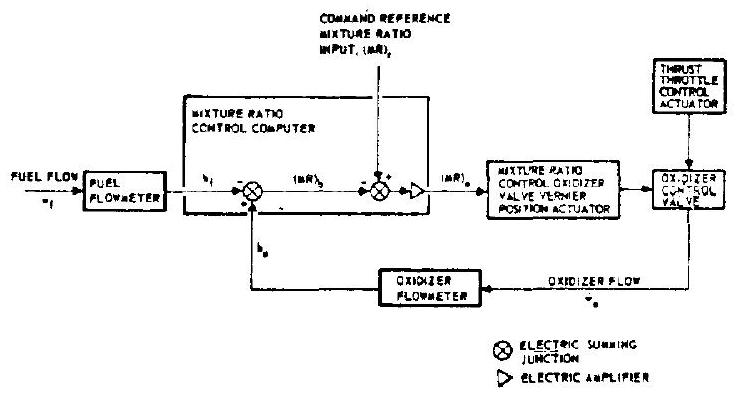 Figure 7-5.-Propellant mixture ratio control loop for the A-4 stage engine.
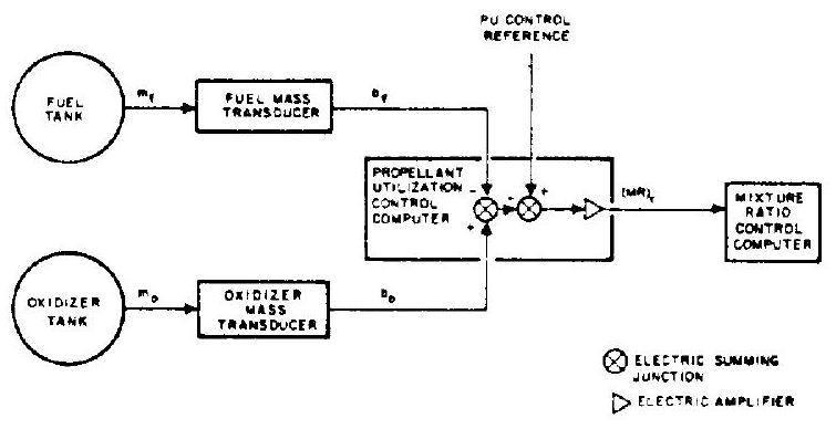 Figure 7-6.-Propellant utilization control system for the A-4 stage propulsion system.
propellant utilization control system is made narrow as compared to that of the mixture-ratio control system,because propellant residual errors may be expected to develop slowly;i.e., initial tanking errors can be corrected over the entire duration of engine operation.
The sensors used in the vehicle tanks may serve additional purposes.In combination with suitable ground equipment,they may permit an automatically controlled loading,high-level limit- ing and topping procedure.In static firings and flight,they may serve as redundant low-level sensors to initiate engine cutoff.For such a complete system,the term"propellant manage- ment system"has come into increased usage.
Apart from throttle valves placed in the main propellant lines,bypass lines have been suc- cessfully applied to vary mixture ratio.Here,a line is tapped off the pump outlet and ducted back to the pump inlet.A servo valve,possibly supported by an orifice,can be varied so that the bypass flow is adjusted from no flow to full bypass flow.
The implementation of closed-loop propellant- utilization control through mixture-ratio control is a major vehicle-to-engine interface area.The requirements or criteria will usually be estab- lished by the vehicle builder and/or user.Close coordination between engine and vehicle designer is essential.
A closed-loop mixture-ratio-and propellant- utilization-control system may not only be used for accurate maintenance of a fixed mixture ratio but it also has the potential for programed mix- ture ratio control(PMR).Here,the mixture ratio is varied during flight,either continuously or in steps.It must be kept in mind that the average mixture ratio still must be equal to the tanked mixture ratio to assure simultaneous propellant depletion.However,by programing a mixture ratio in favor of the heavier component during the early portion of flight,and then switching it in favor of the lighter one,the accelerated vehicle mass is reduced faster.Also,mixture ratio may be programed to provide a higher thrust level during the steeper portion of a trajectory.This provides a better thrust-to-weight ratio in the presence of gravitation,with attendant velocity increase benefits.These methods,possibly in combination,may substantially increase stage payload capacity,since the effects of mixture ratio on performance( )are usually small within a reasonable range(see table 7-1).Optimization can readily be made with the aid of an electronic computer program.In a number of applications, programed mixture ratio control without con- trol,i.e.,open loop mixture ratio control with ,may give best results,simultaneously reducing complexity.
Valves suitable for mixture ratio control will be discussed in section 7.8.
Table 7-1
| Mixture ratio, O/F | Thrust | NPSH | Flow rates | |||
|---|---|---|---|---|---|---|
| Change,percent | +10 | +11 | +12 | -1.3 | +4 | Oxi- dizer |
| -10 | -11 | -12 | +1.3 | -4 | -14 |
General Design Considerations
The precision with which a desired mixture ratio is obtained or maintained is affected con- siderably in open-loop systems,and to some extent in closed-loop systems,by the following: (1)Instrumentation accuracies(in particular, flow and tank-level metering) (2)Machining tolerances of orifices (3)Operating tolerances of regulators (4)Temperature influences on orifices and regulators (5)Density tolerances of the propellants,as a function of temperature and of purity (composition according to specifica- tions;contamination and dilution) (6) Acceleration effects during flight (7) Propellant tank pressure deviations (8) Turbopump speed deviations (9) Differences between fuel and oxidizer pump characteristics as a function of speed (10) Line resistance changes as a function of temperature and for miscellaneous mechanical reasons (11) Temperature effects in rotating machinery
In the following we will discuss important steps toward maintenance of high quality, and toward further improvement in the listed areas, for highest accuracy of mixture-ratio (and propellant-utilization) control.
First, continued improvement of propellant flow-metering devices is imperative. Here, turbine-type flowmeters have achieved a high degree of accuracy (conformance with truth) and precision (repeatability).
The accurate calibration of these meters to most reliable standards is important. Since engine inlet pressures also affect the mixture ratio, pressure measurements of the highest reliability are equally necessary. Wherever possible, the rocket engine design should include vital metering and measuring elements from the outset. Dynamic sensing devices, in particular flow meters, are drastically influenced by their installation configuration. If these end organs, following accurate calibration, remain with the engine through its entire life cycle, including flight, a maximum degree of accuracy is obtained.
The design and machining of all calibration orifices should closely follow accepted standards (see section 7.10). Selection of suitable materials to eliminate or at least to reduce to a minimum, temperature influences and corrosion, is important. The design of orifice holders must prevent the possibility of incorrect (upside down) installation and of distortion of the orifices.
Regulators, if any are used, must be designed for highest accuracy and precision with particular consideration of the medium to be controlled. More detail will be presented in section 7.12.
The purity and composition of the better known propellants are regulated by official government specifications. The designer can expect that approved sources will deliver the propellants in conformance with these. However, subsequent contamination, dilution or alteration is always a possibility and must be prevented by proper design and handling procedures. Many of these, such as cleaning procedures, will be called out in the shop drawings. Furthermore, the design, where applicable, will have to include filters, check valves, and suitable line routing in order to prevent contamination and/or contact with incompatible materials. Note that some propellants may change their properties merely as a function of time, such as hydrogenperoxide, which loses its concentration due to (very slow) decomposition (with attendant gas development), even if absolute cleanliness has been maintained. This affects design conditions in addition to contamination considerations since proper venting devices must be provided. The latter, in turn, have to be designed in such a way that no contaminants, including moisture, can enter the propellant system.
Since mass flow rates delivered by pumps and/or regulated by orifices will be a function of the fluid densities, mixture ratio may be affected accordingly. The densities, in turn, aside from conformance with specifications, will be affected by temperature (noncryogenic fluids) or ambient pressure; i.e., boiling point (cryogenic fluids). To overcome these effects, it may be necessary to temperature-condition the propellants. This may be done by heating or cooling. Or, it may be accomplished by suitable storage, such as shielding against solar radiation. For cryogenic propellants, it is usually sufficient to keep the containers vented to atmosphere until immediately prior to use, since the possible changes of atmospheric pressure at a given altitude can only introduce relatively minor temperature changes. The designer, through a suitable operating sequence (engine schematic) and through provision of vent valves, recirculators, heaters, and other components, can minimize temperature effects.
The actuation of mixture ratio control devices affects the nominal engine performance parameters. Depending on the type of engine, in particular its turbopump characteristics, these effects may be significant. In an actual case, the effects shown in table 7-1 were observed.
It is clear that the vehicle thrust structure must be capable of absorbing the higher thrust loads. Also, the vehicle tanks and their operating pressures must be capable of meeting the
NPSH requirements for extreme mixture ratio excursions. Furthermore, chamber cooling may be affected. During sea-level testing, nozzles with high expansion area ratios may experience jet separation at the lower thrust levels (low ), resulting in vibration, destructive to engine as well as vehicle structure.
Since vehicles are tanked for their nominal mixture ratio, and since engines are calibrated to this ratio, mixture-ratio valve excursions should be small for vehicles which are expended within a few minutes after takeoff. For stages, with long cruising periods prior to operation or reignition, and which use one or two cryogenic propellants, boiloff may have altered the ratio of the propellants in the tanks to such a degree that the system may be called upon to operate at or near its maximum excursion. It is, therefore, vital that the engine designer appraise the vehicle builder of all performance variations as a result of mixture-ratio adjustments, beyond the standard tolerances of the nominal performance values. Also, engine turbopumps must be capable of operating for extended periods with the valve in either extreme position.
A propellant utilization system is a complex system. If required, it must be of the highest quality. Otherwise, it will do more harm than good. Only closest cooperation between vehicle and engine designer will assure opiimum quality. Areas of particular significance to teamwork are:
Selection of the mixture ratio control method.For instance, should the PU system be active during the entire flight duration, or only for the last, say, 30 percent. (Both methods have been successfully used.)
Selection of the mixture ratio control valve specifications.-Should it be a variable orifice, or a bypass valve? What should be the permissible pressure drops, required response rates, and accuracies? In case of sensor failure, should the valve return to the neutral position or remain in its last working position? (Self-locking.)
Selection of the sensors.-Should it be one of several available continously reading types, such as capacitance gages or differential pressure (tank top to bottom) gages? Or should point sensors be employed, such as hot wires (change of heat loss as a function of being immersed in fluid or exposed); switches triggered magnetically by floats; voltage pips induced in station- ary coils by a passing magnet, or others? (The engine designer will be involved in this selection only if the generated signals affect engine components.)
Selection of the best-suited electronic control system.-This will be largely influenced by sensors and control-valve selections.
A propellant utilization system is not a malfunction prevention system. It does not add to vehicle reliability, possibly subtracts from it. Rather, it is a system required to live with a marginal preliminary vehicle design. It is a safe assumption, however, that the first flights of a new vehicle will not be for its ultimate mission. , therefore, will not be a vital necessity for these flights.
Thus, enough time is available to thoroughly investigate, analyze, select, and develop the system. This time should be utilized. Both engine and vehicle builder have facilities and test programs to permit mutual exposure of their selected systems to flight and simulated-flight environment.